---
title: Understanding 4-20 mA Current Loop Systems
description: Understanding 4-20 mA Current Loop Systems
---
[Skip to content](https://help.titanlogix.com/understanding-4-20-ma-current-loop-systems#main-content)
English
Show submenu for translations
[Training Request Form](https://help.titanlogix.com/kb-tickets/new?hsLang=en)
Open main navigation
Close main navigation
- English
Show submenu for translations
- [Training Request Form](https://help.titanlogix.com/kb-tickets/new)
- www.titanlogix.com
www.titanlogix.com
How can we help you?
- There are no suggestions because the search field is empty.
1. [Titan Help Center](https://help.titanlogix.com/?hsLang=en)
2. [Transmitters](https://help.titanlogix.com/transmitters?hsLang=en)
3. [TD100 Transmitter: 4-20mA Output](https://help.titanlogix.com/transmitters?hsLang=en#td100-transmitter-4-20ma-output)
# Understanding 4-20 mA Current Loop Systems
## Introduction
The 4-20 mA signal standard has been widely used in industrial instrumentation since the 1950s. Engineers developed this electronic signaling method to transmit measurement data from sensors to indicators, controllers, and recording devices, replacing the pneumatic and mechanical systems that were commonly used before reliable and affordable electronics became available.
Today, the 4-20 mA current loop remains one of the most common methods of transmitting process measurements because it is simple, reliable, and resistant to signal loss over long cable distances.
### **How a 4-20 mA Loop Works**
The 4-20 mA loop uses a variable current signal to represent the measurement being transmitted by an instrument.
The signal current varies between:
- **4 mA** = Zero measurement (empty, minimum value, or calibrated zero)
- **20 mA** = Full-scale measurement (full, maximum value, or calibrated span)
Unlike a voltage signal, which can be affected by cable resistance and voltage drops over long distances, a current signal maintains its accuracy over long cable runs with minimal signal degradation.
A typical 4-20 mA loop consists of:
- A transmitter (TD100)
- A receiver (PLC, meter, controller, or recorder)
- A two-wire cable connecting the devices
One wire supplies power to the loop, while the other carries the current signal generated by the transmitter. The transmitter adjusts the current flowing in the loop according to the level being measured by the probe.
### **Understanding Zero and Span**
The 4–20 mA standard is designed with an offset, meaning the signal does not start at 0 mA.
- Zero = 4 mA
- Full scale = 20 mA
- Span = 16 mA
The span is calculated as follows:
20 mA − 4 mA = 16 mA
Using a live zero of 4 mA provides several advantages:
- It allows the receiver to distinguish between a valid zero reading and a broken wire.
- It provides a method for signalling fault conditions.
- It improves system reliability during troubleshooting.
A 4–20 mA system is calibrated through proper zero and span adjustments to ensure measurement accuracy throughout its operating range.
It is important to note that the TD100’s current output levels off at the transmitter’s SPILL setting. For the most accurate span, the TD100’s 4 mA point should be set at the bottom of the compartment, and the 20 mA point should be set at the top of the compartment.
Note: The maximum current reading occurs at the SPILL setting and is approximately 18.6 mA. This applies when the 20 mA point is set at the top of the compartment during transmitter programming.
### **Signal Conversion at the Receiver**
The return current in the loop is connected to a specialized receiver input. Inside the receiver, the current signal passes through a sensing resistor, which converts it into a proportional voltage signal. The PLC, meter, display, or data recorder measures this voltage to determine the process value.
Because the receiver converts the current into voltage internally, the measurement remains accurate even over long cable distances.
Designing a Reliable 4–20 mA System
Proper loop design is essential for reliable transmitter operation. The most important consideration is ensuring that sufficient operating voltage is available to power both the receiver and the transmitter.
Before installing the system, determine the analog receiver’s input requirements by measuring its input resistance with a multimeter or consulting the equipment specifications.
### **Receiver Input Resistance Calculations**
For a 10 V analog input:
10 V ÷ 20 mA = 500 Ω
For a 5 V analog input:
5 V ÷ 20 mA = 250 Ω
Knowing the receiver’s input resistance helps determine the minimum supply voltage required for proper operation.
### **TD100 Power Supply Requirements**
When supplying power to the 4–20 mA module through Pin 4 of the TD100, the operating voltage should be approximately 5 V higher than the voltage required by the receiver input.
For example:
- PLC analog input requires 10 V.
- TD100 requires approximately 5 V of operating headroom.
Minimum supply voltage required:
10 V + 5 V = 15 V
If only 12 V is supplied, the transmitter may not have sufficient voltage to produce the full 20 mA output. As a result, the loop may not reach the upper end of its measurement range.
This additional voltage margin is known as headroom.
To ensure proper operation, a higher-voltage power supply may need to be connected to Pin 4 of the TD100. Titan cable harnesses include additional conductors specifically for situations in which extra supply voltage is required.
### **Measuring Analog Input Resistance**
To determine the loop’s operating voltage requirements, use a multimeter set to ohms to measure the resistance between the analog input terminal and ground.
Typical values are:
| Analog Input Voltage | Input Resistance |
| --- | --- |
| 10 V input | 500 Ω |
| 5 V input | 250 Ω |
These measurements can be used to:
- Verify the receiver specifications.
- Calculate the voltage requirements.
- Determine whether additional supply voltage is necessary.
- Confirm compatibility with the vehicle’s battery voltage.
Understanding these values helps ensure that the loop can achieve its full 4–20 mA output range.
### **Advantages of Using a 5 V PLC Input**
A practical solution to voltage limitations is to configure the PLC for a 5 V analog input rather than a 10 V input.
Benefits include:
- Lower operating voltage requirements.
- Less need for an additional external power supply.
- Simpler installation.
- Improved compatibility with vehicle electrical systems.
When using a 5 V analog input, power can typically be supplied by connecting Pin 1 directly to Pin 4 of the TD100.
### **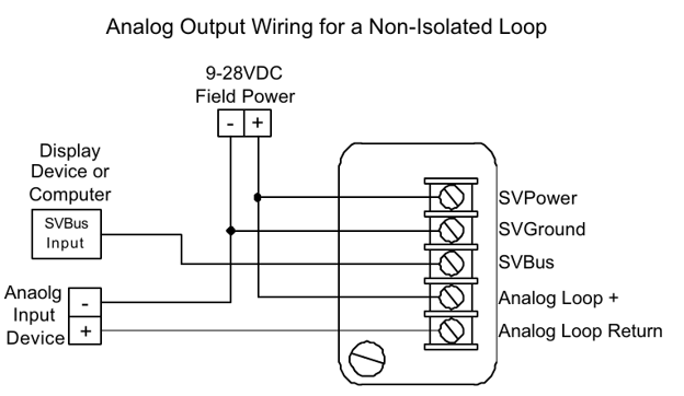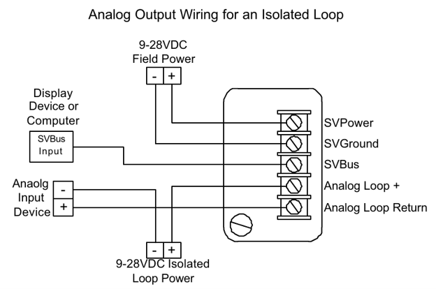**
Power is supplied from a different power source with an isolated Loop
- [Troubleshooting](https://help.titanlogix.com/troubleshooting?hsLang=en#main-content)
- [Error Codes](https://help.titanlogix.com/troubleshooting?hsLang=en#error-codes)
- [Overview](https://help.titanlogix.com/troubleshooting?hsLang=en#overview)
- [Most Common Issues](https://help.titanlogix.com/troubleshooting?hsLang=en#most-common-issues)
- [Alarms](https://help.titanlogix.com/troubleshooting?hsLang=en#alarms)
- [GAUGE Issues](https://help.titanlogix.com/troubleshooting?hsLang=en#gauge-issues)
- [Relays](https://help.titanlogix.com/troubleshooting?hsLang=en#relays)
- [FINCH III Systems (Current)](https://help.titanlogix.com/finch-iii-systems-current?hsLang=en#main-content)
- [FINCH III System Overview](https://help.titanlogix.com/finch-iii-systems-current?hsLang=en#finch-iii-system-overview)
- [Step 1: Installing Hardware (FINCH III Systems)](https://help.titanlogix.com/finch-iii-systems-current?hsLang=en#step-1-installing-hardware-finch-iii-systems)
- [Step 2: Configuring FINCH III Systems](https://help.titanlogix.com/finch-iii-systems-current?hsLang=en#step-2-configuring-finch-iii-systems)
- [Step 3: Testing FINCH III Systems](https://help.titanlogix.com/finch-iii-systems-current?hsLang=en#step-3-testing-finch-iii-systems)
- [Step 4: Operating FINCH III Systems](https://help.titanlogix.com/finch-iii-systems-current?hsLang=en#step-4-operating-finch-iii-systems)
- [Feature Add-On: FINCH III LCR.iQ Integration](https://help.titanlogix.com/finch-iii-systems-current?hsLang=en#feature-add-on-finch-iii-lcr-iq-integration)
- [Feature Add-On: FINCH III Terminal Overfill](https://help.titanlogix.com/finch-iii-systems-current?hsLang=en#feature-add-on-finch-iii-terminal-overfill)
- [Rack Control](https://help.titanlogix.com/finch-iii-systems-current?hsLang=en#rack-control)
- [Feature Add-On: Onboard Pump Control](https://help.titanlogix.com/finch-iii-systems-current?hsLang=en#feature-add-on-onboard-pump-control)
- [FINCH II-W/FINCH II-6W (End of Life)](https://help.titanlogix.com/finch-ii-w-finch-ii-6w-end-of-life?hsLang=en#main-content)
- [Step 1: Installing Hardware (FINCH II-W/6W Systems)](https://help.titanlogix.com/finch-ii-w-finch-ii-6w-end-of-life?hsLang=en#step-1-installing-hardware-finch-ii-w-6w-systems)
- [FINCH II-W/6W Wiring Diagrams](https://help.titanlogix.com/finch-ii-w-finch-ii-6w-end-of-life?hsLang=en#finch-ii-w-6w-wiring-diagrams)
- [Step 2: Configuring FINCH II-W/6W Systems](https://help.titanlogix.com/finch-ii-w-finch-ii-6w-end-of-life?hsLang=en#step-2-configuring-finch-ii-w-6w-systems)
- [3rd party integrations](https://help.titanlogix.com/finch-ii-w-finch-ii-6w-end-of-life?hsLang=en#3rd-party-integrations)
- [FINCH II, FINCH 5332E and FINCH IN-CAB Systems (Discontinued)](https://help.titanlogix.com/finch-ii-finch-5332e-and-finch-in-cab-systems-discontinued?hsLang=en#main-content)
- [FINCH II Display (1 to 2 Compartments)](https://help.titanlogix.com/finch-ii-finch-5332e-and-finch-in-cab-systems-discontinued?hsLang=en#finch-ii-display-1-to-2-compartments)
- [FINCH II Configuration](https://help.titanlogix.com/finch-ii-finch-5332e-and-finch-in-cab-systems-discontinued?hsLang=en#finch-ii-configuration)
- [FINCH 5332E](https://help.titanlogix.com/finch-ii-finch-5332e-and-finch-in-cab-systems-discontinued?hsLang=en#finch-5332e)
- [FINCH 5332E (Red Board)](https://help.titanlogix.com/finch-ii-finch-5332e-and-finch-in-cab-systems-discontinued?hsLang=en#finch-5332e-red-board)
- [FINCH 5332E (Green Board)](https://help.titanlogix.com/finch-ii-finch-5332e-and-finch-in-cab-systems-discontinued?hsLang=en#finch-5332e-green-board)
- [FINCH IN-CAB](https://help.titanlogix.com/finch-ii-finch-5332e-and-finch-in-cab-systems-discontinued?hsLang=en#finch-in-cab)
- [Rack Control Module (RCM) and Titan Supplied API Sockets](https://help.titanlogix.com/finch-ii-finch-5332e-and-finch-in-cab-systems-discontinued?hsLang=en#rack-control-module-rcm-and-titan-supplied-api-sockets)
- [Titan Supplied API Socket Wiring to RCM](https://help.titanlogix.com/finch-ii-finch-5332e-and-finch-in-cab-systems-discontinued?hsLang=en#titan-supplied-api-socket-wiring-to-rcm)
- [Transmitters](https://help.titanlogix.com/transmitters?hsLang=en#main-content)
- [TD100 Transmitter](https://help.titanlogix.com/transmitters?hsLang=en#td100-transmitter)
- [TD100 Transmitter: 4-20mA Output](https://help.titanlogix.com/transmitters?hsLang=en#td100-transmitter-4-20ma-output)
- [Upgrading TD80 \> TD100](https://help.titanlogix.com/transmitters?hsLang=en#upgrading-td80-td100)
- [TD80 (Discontinued)](https://help.titanlogix.com/transmitters?hsLang=en#td80-discontinued)
- [Titan Probes](https://help.titanlogix.com/titan-probes?hsLang=en#main-content)
- [Overview](https://help.titanlogix.com/titan-probes?hsLang=en#overview)
- [Probe: Dual Rod](https://help.titanlogix.com/titan-probes?hsLang=en#probe-dual-rod)
- [Probe: Coaxial](https://help.titanlogix.com/titan-probes?hsLang=en#probe-coaxial)
- [Titan Install & Titan Portal](https://help.titanlogix.com/titan-install-titan-portal?hsLang=en#main-content)
- [Step 1: Register your Company](https://help.titanlogix.com/titan-install-titan-portal?hsLang=en#step-1-register-your-company)
- [User Guide](https://help.titanlogix.com/titan-install-titan-portal?hsLang=en#user-guide)
- [Getting Started](https://help.titanlogix.com/titan-install-titan-portal?hsLang=en#getting-started)
- [Programming your Strapping Chart](https://help.titanlogix.com/titan-install-titan-portal?hsLang=en#programming-your-strapping-chart)
- [Maintenance and Troubleshooting](https://help.titanlogix.com/titan-install-titan-portal?hsLang=en#maintenance-and-troubleshooting)
- [FINCH Display Configuration](https://help.titanlogix.com/titan-install-titan-portal?hsLang=en#finch-display-configuration)
- [Release Notes](https://help.titanlogix.com/titan-install-titan-portal?hsLang=en#release-notes)
- [Administration](https://help.titanlogix.com/titan-install-titan-portal?hsLang=en#administration)
- [SensorLink](https://help.titanlogix.com/sensorlink?hsLang=en#main-content)
- [Overview](https://help.titanlogix.com/sensorlink?hsLang=en#overview)
- [Programming Your Transmitter](https://help.titanlogix.com/sensorlink?hsLang=en#programming-your-transmitter)
- [Configuring your FINCH Display](https://help.titanlogix.com/sensorlink?hsLang=en#configuring-your-finch-display)
- [Troubleshooting](https://help.titanlogix.com/sensorlink?hsLang=en#troubleshooting)
- [Upgrading Titan Products](https://help.titanlogix.com/upgrading-titan-products?hsLang=en#main-content)
- [Upgrade FINCH5332E -\> FINCH II - W or 6W](https://help.titanlogix.com/upgrading-titan-products?hsLang=en#upgrade-finch5332e-finch-ii-w-or-6w)
- [Adding Overfill Prevention to Your Tank](https://help.titanlogix.com/upgrading-titan-products?hsLang=en#adding-overfill-prevention-to-your-tank)
- [Legacy Products](https://help.titanlogix.com/legacy-products?hsLang=en#main-content)
- [Gateway](https://help.titanlogix.com/legacy-products?hsLang=en#gateway)
- [SFT 881](https://help.titanlogix.com/legacy-products?hsLang=en#sft-881)
- [Flo Pro 9100](https://help.titanlogix.com/legacy-products?hsLang=en#flo-pro-9100)
- [TPZ Liquid Level Measurement System](https://help.titanlogix.com/legacy-products?hsLang=en#tpz-liquid-level-measurement-system)
- [FGI Products](https://help.titanlogix.com/legacy-products?hsLang=en#fgi-products)
- [MIC 10](https://help.titanlogix.com/legacy-products?hsLang=en#mic-10)
- [Service Bulletins](https://help.titanlogix.com/service-bulletins?hsLang=en)
[](https://www.titanlogix.com/support/)
The Leader in Mobile Liquid Measurement Solutions
Copyright © 2026, Titan Logix Corp.