---
title: FINCH 5332 Jumpers & Connections
description: Does the TD100 system require periodic maintenance or calibration? The TD100 system does not require periodic maintenance or calibration.
---
[Skip to content](https://help.titanlogix.com/5332ejumperandconnections#main-content)
English
Show submenu for translations
[Training Request Form](https://help.titanlogix.com/kb-tickets/new?hsLang=en)
Open main navigation
Close main navigation
- English
Show submenu for translations
- [Training Request Form](https://help.titanlogix.com/kb-tickets/new)
- www.titanlogix.com
www.titanlogix.com
How can we help you?
- There are no suggestions because the search field is empty.
1. [Titan Help Center](https://help.titanlogix.com/?hsLang=en)
2. [FINCH II, FINCH 5332E and FINCH IN-CAB Systems (Discontinued)](https://help.titanlogix.com/finch-ii-finch-5332e-and-finch-in-cab-systems-discontinued?hsLang=en)
3. [FINCH 5332E](https://help.titanlogix.com/finch-ii-finch-5332e-and-finch-in-cab-systems-discontinued?hsLang=en#finch-5332e)
# FINCH 5332 Jumpers & Connections
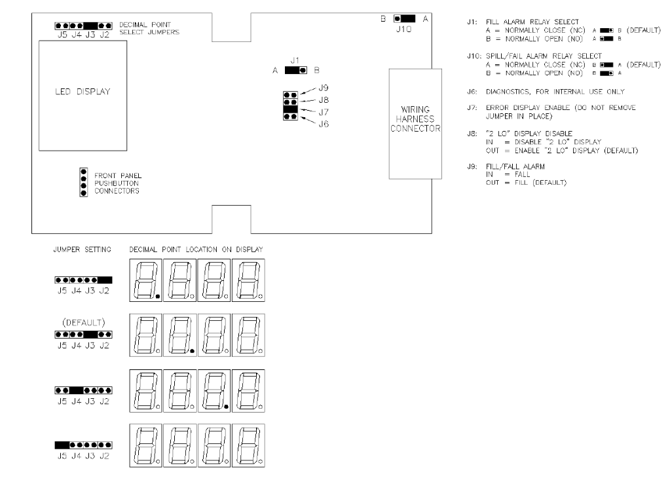
The **Finch 5332** **Internal Display** contains several jumper settings that allow configuration of:
- Decimal point placement
- Onboard relay logic
- FILL/FALL alarm operation
- Display of level readings below 2Lo
**Note:** On the FINCH 5332E, some jumpers are located on the solder side (back side) of the circuit board.
The following jumpers are located on the solder side:
- J1
- J10
- J2, J3, J4, and J5 (mounted in a row)
### **Decimal Point Configuration**
The jumper positions of J2 through J5 determine the decimal point location displayed by the FINCH 5332E.
**
---
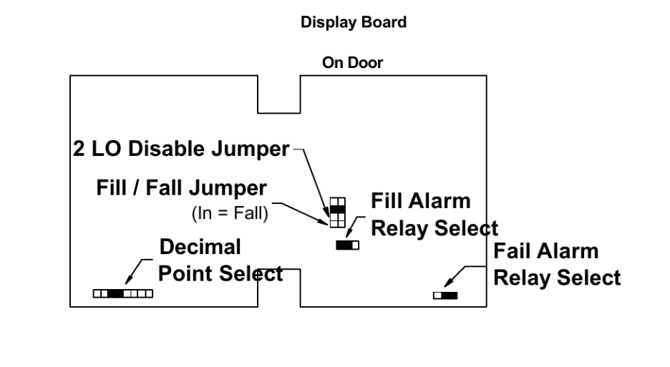
**Finch 5332E Jumper Placement**
### **Jumper Locations**
On the **FINCH 5332E**, jumper placement is located on the **solder side of the circuit board**.
---
### **FILL Relay Configuration (J1)**
The FILL relay operation is controlled by Jumper J1 on the main circuit board.
| Position | Function |
| --- | --- |
| A (Left) | Relay contacts closed when alarming |
| B (Right) | Relay contacts open when alarming |
---
### **SPILL/FAIL Relay Configuration (J10)**
The SPILL/FAIL relay operation is controlled by Jumper J10 on the main circuit board.
| **Position** | **Function** |
| --- | --- |
| A (Right) | Relay contacts closed when alarming |
| B (Left) | Relay contacts open when alarming |
---
### **Wiring Harness Connector**
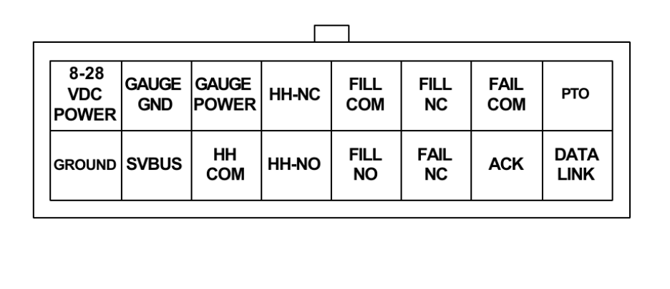
The image below shows the wiring harness connector for both the FINCH 5332 and FINCH 5332E.
**Connector View:** Outside View
---
**Need more help?**
Contact one of our Titan Logix's Service Team members for more technical assistance.
**Phone:** 1-877-462-4085 (ext. 2)
**Email:** [service@titanlogix.com](mailto:service@titanlogix.com)
**Request Training:** [Click Here](https://help.titanlogix.com/kb-tickets/new?hsLang=en)
- [Troubleshooting](https://help.titanlogix.com/troubleshooting?hsLang=en#main-content)
- [Error Codes](https://help.titanlogix.com/troubleshooting?hsLang=en#error-codes)
- [Overview](https://help.titanlogix.com/troubleshooting?hsLang=en#overview)
- [Most Common Issues](https://help.titanlogix.com/troubleshooting?hsLang=en#most-common-issues)
- [Alarms](https://help.titanlogix.com/troubleshooting?hsLang=en#alarms)
- [GAUGE Issues](https://help.titanlogix.com/troubleshooting?hsLang=en#gauge-issues)
- [Relays](https://help.titanlogix.com/troubleshooting?hsLang=en#relays)
- [FINCH III Systems (Current)](https://help.titanlogix.com/finch-iii-systems-current?hsLang=en#main-content)
- [FINCH III System Overview](https://help.titanlogix.com/finch-iii-systems-current?hsLang=en#finch-iii-system-overview)
- [Step 1: Installing Hardware (FINCH III Systems)](https://help.titanlogix.com/finch-iii-systems-current?hsLang=en#step-1-installing-hardware-finch-iii-systems)
- [Step 2: Configuring FINCH III Systems](https://help.titanlogix.com/finch-iii-systems-current?hsLang=en#step-2-configuring-finch-iii-systems)
- [Step 3: Testing FINCH III Systems](https://help.titanlogix.com/finch-iii-systems-current?hsLang=en#step-3-testing-finch-iii-systems)
- [Step 4: Operating FINCH III Systems](https://help.titanlogix.com/finch-iii-systems-current?hsLang=en#step-4-operating-finch-iii-systems)
- [Feature Add-On: FINCH III LCR.iQ Integration](https://help.titanlogix.com/finch-iii-systems-current?hsLang=en#feature-add-on-finch-iii-lcr-iq-integration)
- [Feature Add-On: FINCH III Terminal Overfill](https://help.titanlogix.com/finch-iii-systems-current?hsLang=en#feature-add-on-finch-iii-terminal-overfill)
- [Rack Control](https://help.titanlogix.com/finch-iii-systems-current?hsLang=en#rack-control)
- [Feature Add-On: Onboard Pump Control](https://help.titanlogix.com/finch-iii-systems-current?hsLang=en#feature-add-on-onboard-pump-control)
- [FINCH II-W/FINCH II-6W (End of Life)](https://help.titanlogix.com/finch-ii-w-finch-ii-6w-end-of-life?hsLang=en#main-content)
- [Step 1: Installing Hardware (FINCH II-W/6W Systems)](https://help.titanlogix.com/finch-ii-w-finch-ii-6w-end-of-life?hsLang=en#step-1-installing-hardware-finch-ii-w-6w-systems)
- [FINCH II-W/6W Wiring Diagrams](https://help.titanlogix.com/finch-ii-w-finch-ii-6w-end-of-life?hsLang=en#finch-ii-w-6w-wiring-diagrams)
- [Step 2: Configuring FINCH II-W/6W Systems](https://help.titanlogix.com/finch-ii-w-finch-ii-6w-end-of-life?hsLang=en#step-2-configuring-finch-ii-w-6w-systems)
- [3rd party integrations](https://help.titanlogix.com/finch-ii-w-finch-ii-6w-end-of-life?hsLang=en#3rd-party-integrations)
- [FINCH II, FINCH 5332E and FINCH IN-CAB Systems (Discontinued)](https://help.titanlogix.com/finch-ii-finch-5332e-and-finch-in-cab-systems-discontinued?hsLang=en#main-content)
- [FINCH II Display (1 to 2 Compartments)](https://help.titanlogix.com/finch-ii-finch-5332e-and-finch-in-cab-systems-discontinued?hsLang=en#finch-ii-display-1-to-2-compartments)
- [FINCH II Configuration](https://help.titanlogix.com/finch-ii-finch-5332e-and-finch-in-cab-systems-discontinued?hsLang=en#finch-ii-configuration)
- [FINCH 5332E](https://help.titanlogix.com/finch-ii-finch-5332e-and-finch-in-cab-systems-discontinued?hsLang=en#finch-5332e)
- [FINCH 5332E (Red Board)](https://help.titanlogix.com/finch-ii-finch-5332e-and-finch-in-cab-systems-discontinued?hsLang=en#finch-5332e-red-board)
- [FINCH 5332E (Green Board)](https://help.titanlogix.com/finch-ii-finch-5332e-and-finch-in-cab-systems-discontinued?hsLang=en#finch-5332e-green-board)
- [FINCH IN-CAB](https://help.titanlogix.com/finch-ii-finch-5332e-and-finch-in-cab-systems-discontinued?hsLang=en#finch-in-cab)
- [Rack Control Module (RCM) and Titan Supplied API Sockets](https://help.titanlogix.com/finch-ii-finch-5332e-and-finch-in-cab-systems-discontinued?hsLang=en#rack-control-module-rcm-and-titan-supplied-api-sockets)
- [Titan Supplied API Socket Wiring to RCM](https://help.titanlogix.com/finch-ii-finch-5332e-and-finch-in-cab-systems-discontinued?hsLang=en#titan-supplied-api-socket-wiring-to-rcm)
- [Transmitters](https://help.titanlogix.com/transmitters?hsLang=en#main-content)
- [TD100 Transmitter](https://help.titanlogix.com/transmitters?hsLang=en#td100-transmitter)
- [TD100 Transmitter: 4-20mA Output](https://help.titanlogix.com/transmitters?hsLang=en#td100-transmitter-4-20ma-output)
- [Upgrading TD80 \> TD100](https://help.titanlogix.com/transmitters?hsLang=en#upgrading-td80-td100)
- [TD80 (Discontinued)](https://help.titanlogix.com/transmitters?hsLang=en#td80-discontinued)
- [Titan Probes](https://help.titanlogix.com/titan-probes?hsLang=en#main-content)
- [Overview](https://help.titanlogix.com/titan-probes?hsLang=en#overview)
- [Probe: Dual Rod](https://help.titanlogix.com/titan-probes?hsLang=en#probe-dual-rod)
- [Probe: Coaxial](https://help.titanlogix.com/titan-probes?hsLang=en#probe-coaxial)
- [Titan Install & Titan Portal](https://help.titanlogix.com/titan-install-titan-portal?hsLang=en#main-content)
- [Step 1: Register your Company](https://help.titanlogix.com/titan-install-titan-portal?hsLang=en#step-1-register-your-company)
- [User Guide](https://help.titanlogix.com/titan-install-titan-portal?hsLang=en#user-guide)
- [Getting Started](https://help.titanlogix.com/titan-install-titan-portal?hsLang=en#getting-started)
- [Programming your Strapping Chart](https://help.titanlogix.com/titan-install-titan-portal?hsLang=en#programming-your-strapping-chart)
- [Maintenance and Troubleshooting](https://help.titanlogix.com/titan-install-titan-portal?hsLang=en#maintenance-and-troubleshooting)
- [FINCH Display Configuration](https://help.titanlogix.com/titan-install-titan-portal?hsLang=en#finch-display-configuration)
- [Release Notes](https://help.titanlogix.com/titan-install-titan-portal?hsLang=en#release-notes)
- [Administration](https://help.titanlogix.com/titan-install-titan-portal?hsLang=en#administration)
- [SensorLink](https://help.titanlogix.com/sensorlink?hsLang=en#main-content)
- [Overview](https://help.titanlogix.com/sensorlink?hsLang=en#overview)
- [Programming Your Transmitter](https://help.titanlogix.com/sensorlink?hsLang=en#programming-your-transmitter)
- [Configuring your FINCH Display](https://help.titanlogix.com/sensorlink?hsLang=en#configuring-your-finch-display)
- [Troubleshooting](https://help.titanlogix.com/sensorlink?hsLang=en#troubleshooting)
- [Upgrading Titan Products](https://help.titanlogix.com/upgrading-titan-products?hsLang=en#main-content)
- [Upgrade FINCH5332E -\> FINCH II - W or 6W](https://help.titanlogix.com/upgrading-titan-products?hsLang=en#upgrade-finch5332e-finch-ii-w-or-6w)
- [Adding Overfill Prevention to Your Tank](https://help.titanlogix.com/upgrading-titan-products?hsLang=en#adding-overfill-prevention-to-your-tank)
- [Legacy Products](https://help.titanlogix.com/legacy-products?hsLang=en#main-content)
- [Gateway](https://help.titanlogix.com/legacy-products?hsLang=en#gateway)
- [SFT 881](https://help.titanlogix.com/legacy-products?hsLang=en#sft-881)
- [Flo Pro 9100](https://help.titanlogix.com/legacy-products?hsLang=en#flo-pro-9100)
- [TPZ Liquid Level Measurement System](https://help.titanlogix.com/legacy-products?hsLang=en#tpz-liquid-level-measurement-system)
- [FGI Products](https://help.titanlogix.com/legacy-products?hsLang=en#fgi-products)
- [MIC 10](https://help.titanlogix.com/legacy-products?hsLang=en#mic-10)
- [Service Bulletins](https://help.titanlogix.com/service-bulletins?hsLang=en)
[](https://www.titanlogix.com/support/)
The Leader in Mobile Liquid Measurement Solutions
Copyright © 2026, Titan Logix Corp.